This is the workflow that carried one 60-entity schema from first sketch to production with the ERD staying authoritative the whole way, in four phases: design the full model with legends marking the bounded contexts, hand each legend’s exported SQL to an AI coding agent to implement, connect a copy of the design to the live database once, then refresh and merge the diagram after every migration. It exists because of a moment in every project where the schema design dies. Not when it’s drawn - drawing it is the fun part - but at the handoff, when implementation starts. The diagram says subscriptions has nine fields; someone now has to retype those nine fields as an ORM model, then do it again for fifty-nine more entities. From that day forward the code is the model, the database evolves through migrations, and the diagram becomes a souvenir.
The tooling world’s answer is to regenerate the diagram from the code, and the duct tape shows. Prisma users reach for a diagram generator and find schema generation fails under WSL because of a puppeteer dependency three layers down. Rails users run rake erd into a Graphviz-is-not-in-your-path error that persists after Graphviz is installed. Even when these pipelines work, they emit an auto-laid-out artifact - a rendering, not a design.
It doesn’t have to work this way. Here is the full loop from that real project - designed once, shipped context by context - where the diagram stays the design the whole way through. It is an ERD single source of truth workflow, and at no point does the ERD write a single statement to the database.
Phase 1: Design the whole model up front
Before any code, the entire schema goes onto the canvas: entities aligned, relationship lines routed so they read cleanly, and - this is the load-bearing part - legends drawn around each group of entities to mark the bounded contexts. Identity, catalog, billing, fulfillment: each becomes a named, colored region, and coloring the entities makes every context traceable by hue. This is domain-driven design database schema work in its natural habitat - you are deciding where the boundaries fall while moving boxes is still free.
Design up front does not mean design perfectly. It means capturing everything you currently know about the domain in one picture, so that implementation starts from a map instead of a blank file. Sixty entities sounds heavy; on an infinite canvas with locked legends - drag the region and everything inside moves as one block - it is an afternoon of thinking made visible.
Phase 2: Implement one context at a time, with AI writing the code
Now the trick that makes the design executable. Right-click a legend and Schemity exports the SQL for every entity inside it - the whole bounded context as CREATE TABLE statements in one action. That SQL, plus one line of instruction (“this is the billing module, generate the models”), goes to Claude Code, which writes the ORM models - and sometimes the CRUD layer - for that context.
Then the direction of authority flips, deliberately: migration files are generated from those models and applied by the project’s own source code, the way the ORM intends. The ERD provided the spec; the code owns the database from here. Notice what the diagram tool did not do - it never connected as a writer, never applied DDL. The bounded context ERD was the prompt, and a context at a time turns out to be the right unit for AI codegen too: small enough to fit in a model’s head, large enough to be a coherent module.
This is a different intersection of AI and ERDs than letting an AI agent work on the diagram itself - here the human designed, and AI does the typing. What they share is the privacy shape: private AI database design means your schema goes only where you point it, from a local file on your machine.
Phase 3: Connect a copy of the design to the live database
With the first contexts migrated into the local database, the design itself becomes the connected diagram - nothing is re-arranged by hand. Duplicate the design’s JSON file, keep the original as the plan, and connect the copy to the database. A design connected to a database that already has tables is merged, not replaced: the copy opens as the database’s real schema wearing your design. Every migrated table keeps its designed position, size, and color, the legends stay where you drew them, and relationship lines keep their routes - even where the ORM named the foreign key its own way (Django hashes constraint names, GORM prefixes them with fk_), because a relation is matched by the columns it joins, not by its constraint name. The whole merge arrives as one unsaved change: read it in History, then save it, or close without saving and the file is exactly as it was.
Why a copy and not the design itself? In this merge the database decides what exists, so tables that live only in the diagram are dropped. Connect the original while only billing is migrated and every context you have not built yet would vanish from it. Two files, two jobs: the design holds the plan for what is not built, and the connected copy mirrors what is. From this point the connected diagram is the living mirror of the real schema. Each legend is also one right-click away from becoming a context view - Import to context views brings everything inside the region into a focused sub-diagram, so the bounded contexts you designed become the views you navigate day to day.
Phase 4: Refresh & merge, repeat forever
Eventually the code outgrows the original design - it always does. A new table A belongs in context C1. The smoothest path draws it first: sketch A inside C1 on the connected diagram, where it wears a dashed border because the database does not have it yet, right-click the legend, and hand its SQL to Claude Code. The ORM model changes, the generated migration runs, and then the update to the diagram is the whole point of this post: press Refresh & merge (the Reset ERD dropdown, Cmd+Shift+R, or the command palette). Schemity re-reads the live database onto the diagram on screen, the database confirms A, and the dashed draft turns solid in the place you drew it. Nothing moves.
If A arrived another way - a teammate’s migration, an agent working straight in the codebase - the same refresh brings it in placed clear of the rest, ready to drag into C1; or, if it was designed in the original tab first, copy that context and paste, and the merge-aware paste snaps A to its designed position, size, and color while touching nothing else. Either way, everything already arranged keeps its layout, legends, and line routes, and anything dropped from the database is gone from the picture. The refresh is one unsaved change you review before saving, and Undo takes it back. (Reset ERD, the button next to it, is the other tool: it starts over from the saved file and discards unsaved edits - right for throwing work away, wrong for this loop.) Updating the diagram stops being a job and becomes a keystroke.
From here the loop is closed: design informs code, code migrates the database, the database refreshes the diagram in place, and the diagram - grouped back into contexts - informs the next round of design.
The trick: let the diff write the prompt
Adding a table is the easy change. The subtler case is modifying what exists - splitting a field, tightening a type, hanging a new constraint on an old column. The default move is to describe the change to Claude Code in prose and let it edit the model files, and then you inherit a review job: did it interpret “split the address out of customers” the way you meant?
There is a better move, and it uses the diagram as the editor. Make the change on the connected ERD - the same gesture as designing - and press Save. Schemity compares the edited diagram against the live database and shows the migration SQL diff: the exact ALTER statements, in your engine’s dialect, that your edit implies. Now don’t apply it. Copy that SQL, hand it to Claude Code along with the reason for the change, and it updates the ORM model precisely - because a SQL diff is an unambiguous spec in a way prose never is. The review burden collapses: you already saw the intended change, statement by statement, before the AI touched a file.
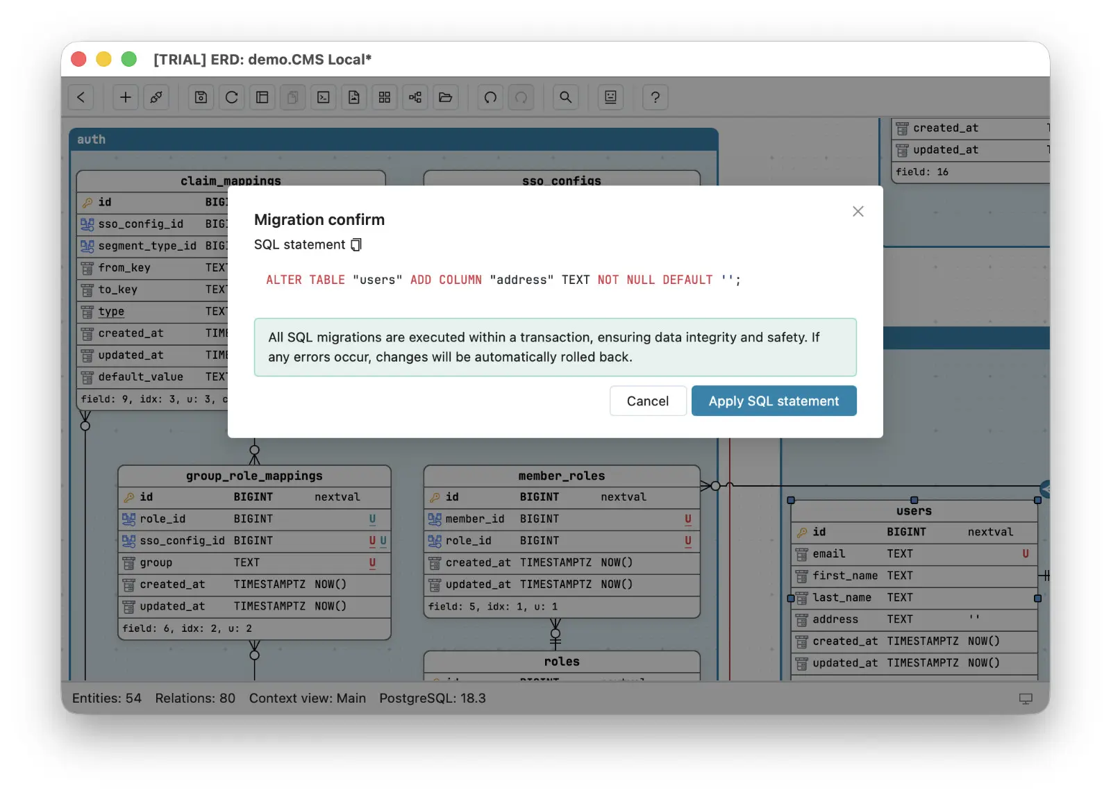
From there the loop runs as always: the ORM generates its migration files from the changed model, your source code applies them, and Refresh & merge brings your own change back to the canvas - confirmed by the database itself. One design gesture became a precise diff, the diff became the prompt, the prompt became code, and the code migrated the database. You never left the canvas to specify the change.
The ERD never writes to the database
Run the whole loop again in your head and count the write paths to the database. There is exactly one: the ORM’s migrations, executed by your source code. The ERD reads - at reverse-engineering, at every re-sync - and never writes, not because the tool couldn’t, but because the workflow makes it unnecessary. Even the migration diff, the one feature built to write, spends its life here as a messenger: a generated spec you hand to the AI, never a statement you run. The canvas keeps the boundary honest, too: anything the database has not confirmed yet - a sketched table, an over-eager paste - wears a dashed border until a successful migration makes it real, and saving warns you about entities that exist nowhere but the picture.
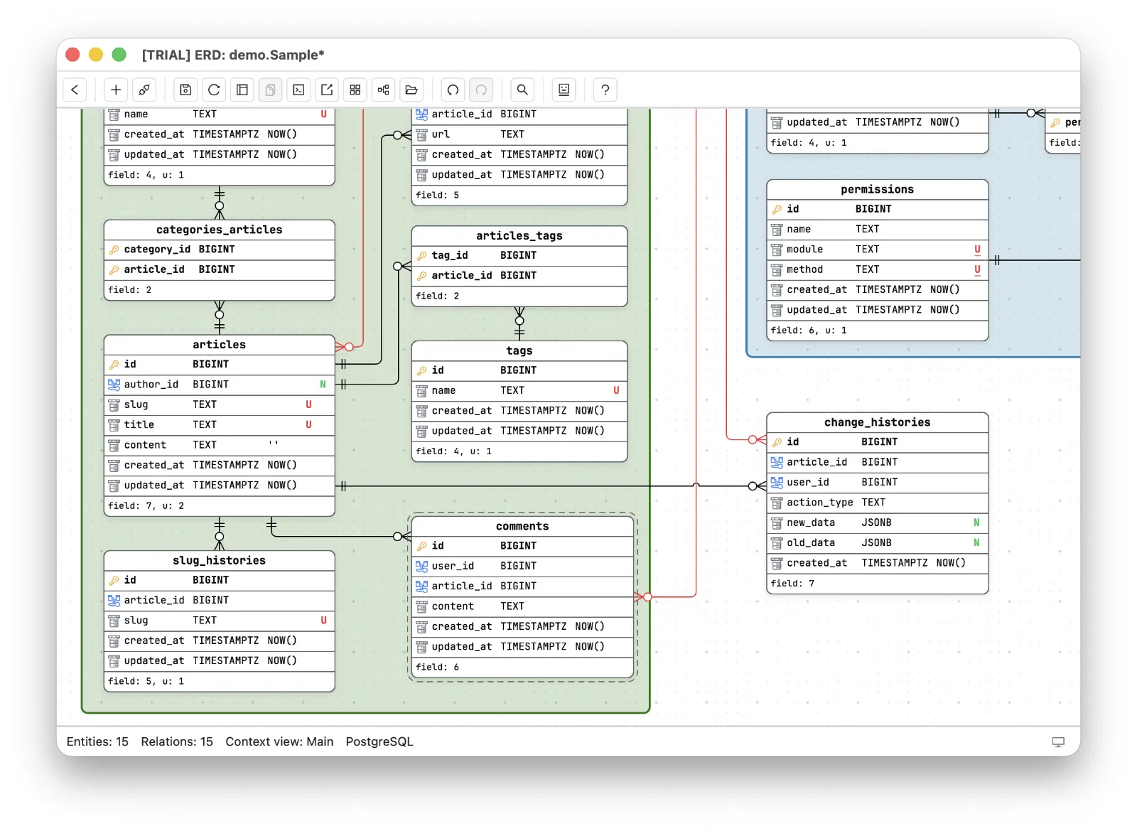 That asymmetry is what lets you point a diagram tool at a database without the low-grade fear that a canvas edit becomes a DDL statement.
It also explains why this works as an database design software workflow with nothing to configure: both diagrams are plain JSON files in the repo, committed alongside the models they specified, so the design history and the code history live in the same Git log. No sync service, no diagram server, no write credentials - a database design software, a local database, and an AI assistant that receives exactly the SQL you right-clicked.
Design first, so the thinking happens while change is free. Ship by context, so every unit of work has a boundary. Let the database drive the diagram after that, so the truth maintains itself. Sixty entities in, the diagram is still the design - which is all anyone ever wanted from an ERD.
Frequently asked questions
How do I turn an ERD design into a real database?
Design the whole model first, group it into bounded contexts with legends, then export the SQL of one legend at a time and hand it to your AI coding agent to generate ORM models and migrations. The ORM migration stays the only write path to the database - the ERD never writes to it directly.
How do I keep the ERD in sync after the schema changes?
Through re-sync, with the live database as the source of truth. After a migration runs outside Schemity, such as an ORM's, run Refresh & merge (Cmd+Shift+R): it re-reads the database onto the diagram on screen as one unsaved change. Entities and relationship lines keep their layout and routes, dashed drafts the migration created turn solid in place, dropped tables disappear, and new ones appear ready to drag into place.
Should my database design software apply changes to the database directly?
Not in this workflow. When you edit the ERD, Schemity generates the migration SQL diff, but instead of applying it you use that diff as an unambiguous prompt for your coding agent to write the ORM migration - keeping one write path and a full migration history.